Circuit Library › Amplifiers › power
2 W Bipolar Power Amplifier, 7 MHz (MJE181)
Bench sheet (PDF)Schematic PDFSPICE netlist (.cir)KiCad project (.zip)
- pout_w 2.25 at 7 MHz book
- pout_w 4.1 at 7 MHz simulated
- pdc_w 6.5 at 7 MHz simulated
What it does
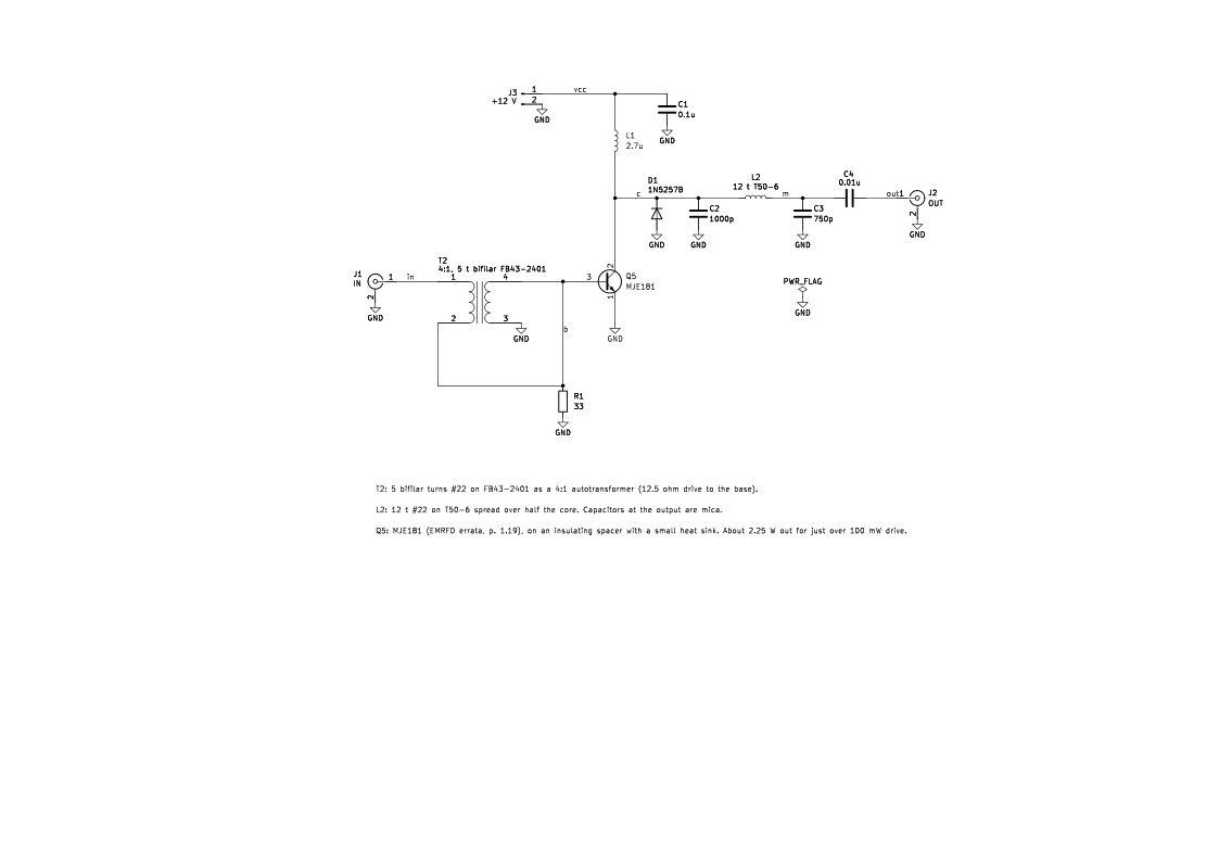
The final amplifier for a 40 m QRP CW transmitter. About 100 mW in gives about 2.25 W out into 50 Ω (EMRFD p. 1.19).
How it works
Q5 runs class C with its base returned to ground through 33 Ω. T2, 5 bifilar turns on an FB43-2401 wired as a 4:1 autotransformer, steps the 50 Ω drive down to about 12.5 Ω at the base. The collector is fed through a 2.7 µH RFC. A pi network (1000 pF, L2, 750 pF) transforms the 50 Ω load to the collector load line and filters harmonics. D1, a 33 V zener, clamps collector peaks.
The simulation gives 4.1 W out for 100 mW available drive. That's well above the book's 2.25 W, because the MJE181 model and the ideal parts are optimistic. Treat it as simulated only.
Building it
- Q5: MJE181, per the EMRFD errata. The figure's 2N5321 is discontinued. Mount it with an insulating spacer; a small heat sink helps.
- T2: 5 bifilar turns of #22 on an FB43-2401, connected as a 4:1 step-down.
- L2: 12 turns of #22 on a T50-6, spread over half the core.
- Use mica for the 1000 pF and 750 pF output capacitors.
- Always follow it with a low-pass filter such as the 40 m 7th-order Chebyshev LPF.
Tuning and testing
Use a 50 Ω dummy load and a power meter. Raise the drive slowly to about 100 mW and watch the collector current and the heat sink temperature. Squeeze or spread L2 for the best output.
Where it comes from
The power amplifier of the beginner's experimental transmitter in Experimental Methods in RF Design, Chapter 1.
Simulation
Simulated in ngspice from the schematic netlist. Not a measurement.
Parts list
| Ref | Value | Qty |
|---|---|---|
| C1 | 0.1u | 1 |
| C2 | 1000p | 1 |
| C3 | 750p | 1 |
| C4 | 0.01u | 1 |
| D1 | 1N5257B | 1 |
| J1 | IN | 1 |
| J2 | OUT | 1 |
| J3 | +12 V | 1 |
| L1 | 2.7u | 1 |
| L2 | 12 t T50-6 | 1 |
| Q5 | MJE181 | 1 |
| R1 | 33 | 1 |
| T2 | 4:1, 5 t bifilar FB43-2401 | 1 |
SPICE netlist
References
- EMRFD Fig 1.35, p. 1.19 (errata: affects-circuit: Fig 1.35: change Q5 from the discontinued 2N5321 to an MJE181, mounted with an insulated spacer; a small heat sink helps and efficiency is lower than with the 2N5321. Two text-only fixes on the same page (about 10 dB; heat sink).)