Circuit Library › Amplifiers › small-signal
W7EL Two-Transistor Feedback Buffer Amplifier
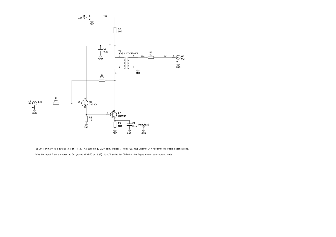
Bench sheet (PDF)Schematic PDFSPICE netlist (.cir)KiCad project (.zip)
- vgain_db -9.1 at 7 MHz simulated
- vgain_db -7.7 at 14 MHz simulated
- icc_ma 11 simulated
What it does
A small buffer that sits after a VFO or crystal oscillator. It has a high-impedance input so it barely loads the oscillator, and a transformer output that drives a 50 Ω load.
How it works
Q1 and Q2 form a two-transistor feedback pair like the MAR MMIC circuits. The 27 kΩ (R4) from Q2's collector back to Q1's base and the 10 kΩ input resistor (R1) set the closed-loop gain. Q2's emitter has 180 Ω bypassed by 0.1 µF. T1 steps the collector impedance down to the 50 Ω output, which gives more available gain than a resistive-load MAR-style stage (EMRFD p. 2.27).
Simulated with a 20:5 t T1 (A_L and k assumed, see the deck): about −9 dB from the input voltage to the voltage across 50 Ω at 7 MHz, and 11 mA from 12 V. These are simulated, not book values.
Building it
- Q1, Q2: 2N3904, or MMBT3904 for SMD. This is a QRPedia substitution; the figure doesn't name the type.
- T1: for 7 MHz, 20-turn primary and 5-turn output link on an FT-37-43 (EMRFD p. 2.27 text). The figure gives no turns.
- Drive the input from a source at DC ground (EMRFD p. 2.27).
- Bandwidth depends on T1. Too little reactance at low frequencies causes severe distortion.
Tuning and testing
There's nothing to tune. Check the DC collector voltages, then drive with a signal generator into 50 Ω and look at the output on a scope.
Where it comes from
A buffer by Roy Lewallen, W7EL, shown in Experimental Methods in RF Design as Fig 2.79, often used as an oscillator buffer.
Simulation
Simulated in ngspice from the schematic netlist. Not a measurement.
Parts list
| Ref | Value | Qty |
|---|---|---|
| C1,C2 | 0.1u | 2 |
| J1 | IN | 1 |
| J2 | OUT | 1 |
| J3 | +12 V | 1 |
| Q1,Q2 | 2N3904 | 2 |
| R1 | 10K | 1 |
| R2 | 1K | 1 |
| R3 | 100 | 1 |
| R4 | 27K | 1 |
| R5 | 180 | 1 |
| R6 | 47 | 1 |
| T1 | 20:5 t FT-37-43 | 1 |
SPICE netlist
References
- EMRFD Fig 2.79, p. 2.27 (errata: text-only: Two text corrections on p. 2.27: the sentence beginning "This IC..." is replaced, and a Greek Omega should read W (watt). Neither changes the schematic.)