Circuit Library › Filters › low-pass
40 m 7th-order Chebyshev Low-Pass Filter (7.5 MHz)
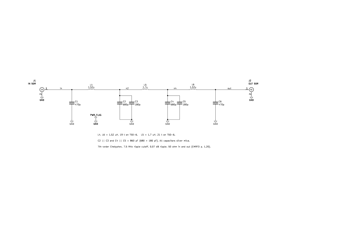
Bench sheet (PDF)Schematic PDFSPICE netlist (.cir)KiCad project (.zip)
- fc_mhz 7.5 book
- ripple_db 0.07 book
- il_db 0.11 at 7 MHz book
- fc_mhz 7.5 simulated
- f3db_mhz 8.08 simulated
- ripple_db 0.076 simulated
- il_db 0.24 at 7 MHz simulated
- rl_db 17.6 simulated
- stopband_db 51.4 at 14 MHz simulated
- stopband_db 78.9 at 21 MHz simulated
What it does
It cleans up a 40 m QRP transmitter's output. It passes 7.0–7.3 MHz with almost no loss and cuts the harmonics (14, 21, 28 MHz) by 50 to 100 dB.
How it works
It's a 7-element Chebyshev low-pass: four shunt capacitors and three series toroid inductors, designed for 50 Ω at both ends. The odd 0.07 dB ripple was chosen so standard capacitor values fit (EMRFD p. 1.20). The LC filter designer gives 467 pF / 1.521 µH / 859 pF / 1.696 µH for the same specification, within 1% of the book.
Building it
- Silver mica capacitors; each 860 pF is a 680 pF and a 180 pF in parallel.
- L4 and L6: 19 turns on T50-6 (1.52 µH). L5: 21 turns on T50-6 (1.7 µH). Spread or squeeze the turns to tune.
- The book housed it in a small aluminum box with coax connectors and found the shielding important.
Tuning and testing
Sweep with a 50 Ω generator and detector, or a NanoVNA, from 1 to 30 MHz. Expect under 0.25 dB loss at 7 MHz and a return loss better than about 17 dB across 40 m.
Where it comes from
The low-pass filter for the beginner's experimental transmitter in Experimental Methods in RF Design, Chapter 1.
Simulation
Simulated in ngspice from the schematic netlist. Not a measurement.
Parts list
| Ref | Value | Qty |
|---|---|---|
| C1,C6 | 470p | 2 |
| C2,C4 | 680p | 2 |
| C3,C5 | 180p | 2 |
| J1 | IN 50R | 1 |
| J2 | OUT 50R | 1 |
| L4,L6 | 1.52u | 2 |
| L5 | 1.7u | 1 |
SPICE netlist
References
- EMRFD Fig 1.37, p. 1.20