Circuit Library › Matching › balun
1:1 Trifilar True (Current) Balun
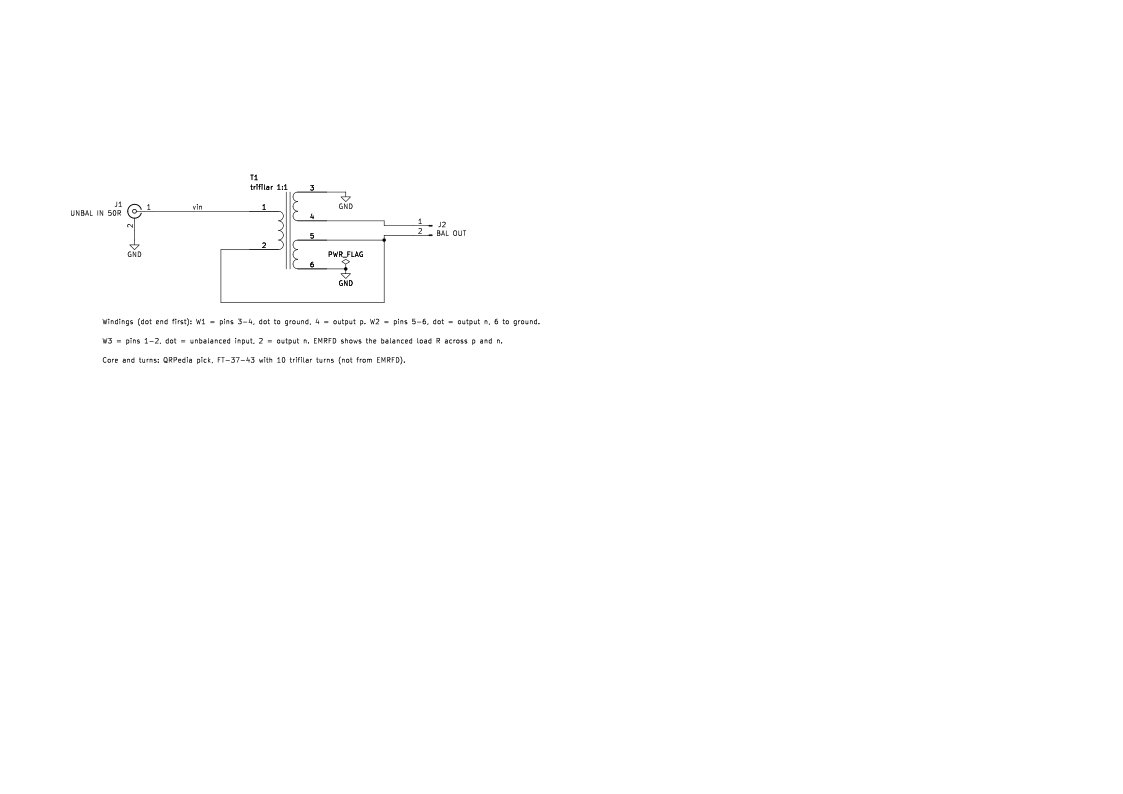
Bench sheet (PDF)Schematic PDFSPICE netlist (.cir)KiCad project (.zip)
- il_db 0.02 at 14 MHz simulated
- il_db 1.4 at 14 MHz simulated
- rl_db 17.6 at 30 MHz simulated
What it does
Connects an unbalanced 50 Ω coax line to a balanced 50 Ω load, such as a dipole, and forces equal and opposite currents in the two output leads.
How it works
Three windings on one core. Two carry the signal to each side of the load; the third ties the output's virtual center to ground reference, so common-mode current sees a high impedance. Performance depends strongly on coupling: with k = 0.999 the simulated loss is 0.02 dB at 14 MHz, but with k = 0.99 it rises to 1.4 dB (simulated, both).
Building it
- Core and turns aren't in EMRFD. QRPedia's pick is 10 trifilar turns on an FT-37-43, for receive or low power.
- Twist the three wires together before winding to keep coupling tight. Pins 1, 3 and 5 are the dot ends.
Tuning and testing
Terminate the output in 50 Ω and measure return loss at the input with a return-loss bridge across the bands.
Where it comes from
A 1:1 current balun from Experimental Methods in RF Design, Chapter 3.
Simulation
Simulated in ngspice from the schematic netlist. Not a measurement.
Parts list
| Ref | Value | Qty |
|---|---|---|
| J1 | UNBAL IN 50R | 1 |
| J2 | BAL OUT | 1 |
| T1 | trifilar 1:1 | 1 |
SPICE netlist
References
- EMRFD Fig 3.78, p. 3.35