Circuit Library › Power › linear-regulator
LM317 Dual-Output Bench Supply
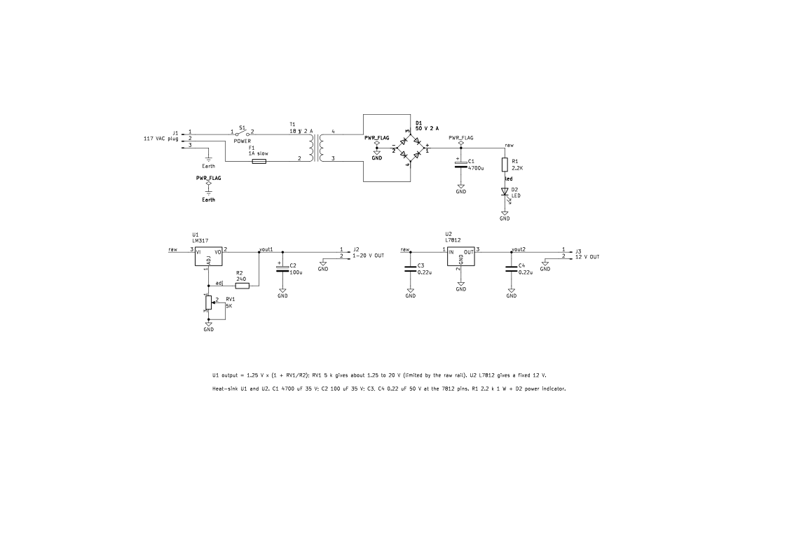
Bench sheet (PDF)Schematic PDFSPICE netlist (.cir)KiCad project (.zip)
- vout_v 11.74 simulated
- vout_v 11.98 simulated
- vraw_v 20.0 simulated
What it does
A mains bench supply with two regulated outputs from LM317s, one adjustable, for powering QRP projects.
How it works
A transformer, bridge rectifier and filter capacitor make a raw DC rail. Each LM317 holds 1.25 V between its output and adjust pins, so the divider resistors set the output. Output 1 uses a pot (RV1) for adjustment. The simulation, with an assumed 18 V rms secondary, shows the raw rail at 20.0–21.2 V at 1 A total load, so the top of the adjustment range (20 V) isn't reachable at full load (simulated).
Building it
- Mains wiring is dangerous. Fuse the primary, insulate everything, and bond the chassis to the earth pin (J1's ground goes to Earth, not to the DC ground).
- Heat-sink both regulators.
Tuning and testing
Bring it up first with no load and check both outputs. Then load each output to 0.5 A and check for ripple and heat.
Where it comes from
The beginner's bench supply in Experimental Methods in RF Design, Chapter 1.
Simulation
Simulated in ngspice from the schematic netlist. Not a measurement.
Parts list
| Ref | Value | Qty |
|---|---|---|
| C1 | 4700u | 1 |
| C2 | 100u | 1 |
| C3,C4 | 0.22u | 2 |
| D1 | 50 V 2 A | 1 |
| D2 | LED | 1 |
| F1 | 1A slow | 1 |
| J1 | 117 VAC plug | 1 |
| J2 | 1-20 V OUT | 1 |
| J3 | 12 V OUT | 1 |
| R1 | 2.2K | 1 |
| R2 | 240 | 1 |
| RV1 | 5K | 1 |
| S1 | POWER | 1 |
| T1 | 18 V 2 A | 1 |
| U1 | LM317 | 1 |
| U2 | L7812 | 1 |
SPICE netlist
References
- EMRFD Fig 1.24, p. 1.15 (errata: text-only: p. 1.15: "Farads" should be lowercase "farads". Text only.)