Circuit Library › Receivers › direct-conversion
Direct-Conversion Receiver, 40 m (TUF-1 DBM)
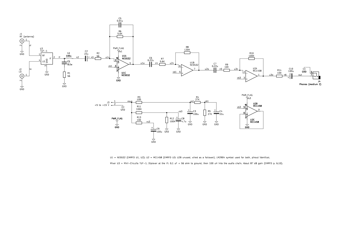
Bench sheet (PDF)Schematic PDFSPICE netlist (.cir)KiCad project (.zip)
- gain_db 87 book
- gain_db 85.3 simulated
- conv_loss_db 9.6 simulated
What it does
A complete direct-conversion receiver back end for 40 m. RF and a local oscillator go into a diode ring mixer, and the audio difference comes out to headphones.
How it works
The TUF-1 mixer multiplies the RF with the LO. Its IF port feeds a diplexer: 0.1 µF plus 56 Ω to ground terminates the mixer at RF, and a 100 µH choke passes audio on. A low-noise NE5532 stage and further op-amp stages give about 87 dB of audio gain (EMRFD p. 6.10). The simulation gives 85.3 dB at 1 kHz (simulated).
Building it
- Drive the LO port at about +7 dBm from a clean oscillator.
- Headphone impedance isn't stated in EMRFD; the simulation assumes 600 Ω.
- Keep the audio input stage away from AC hum sources, and shield it.
Tuning and testing
Inject a weak signal at 7.0 MHz with the LO 1 kHz away and listen for a clean tone. Check for hum and microphonics.
Where it comes from
A direct-conversion receiver example from Experimental Methods in RF Design, Chapter 6.
Simulation
Simulated in ngspice from the schematic netlist. Not a measurement.
Parts list
| Ref | Value | Qty |
|---|---|---|
| C1 | 0.1u | 1 |
| C2,C4 | 22u | 2 |
| C3,C9,C10,L1 | 100u | 4 |
| C5 | 0.01u | 1 |
| C6,C7 | 0.22u | 2 |
| C8 | 4.7u | 1 |
| J1 | RF (antenna) | 1 |
| J2 | LO | 1 |
| J3 | +5 to +15 V | 1 |
| J4 | Phones (medium Z) | 1 |
| R1,R2 | 56 | 2 |
| R3,R13,R14 | 100 | 3 |
| R4,R5 | 27K | 2 |
| R6,R7 | 5.6K | 2 |
| R8 | 130K | 1 |
| R9 | 10K | 1 |
| R10-R12 | 100K | 3 |
| U1 | NE5532 | 1 |
| U2 | MC1458 | 1 |
| U3 | TUF-1 | 1 |
SPICE netlist
References
- EMRFD Fig 6.29, p. 6.10
- Mini-Circuits TUF-1+ datasheet (REV. A, M151107), p. 1