Circuit Library › Oscillators › lc-vfo
Hartley VFO with 2N4416 JFET
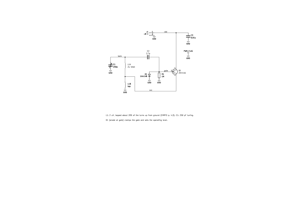
Bench sheet (PDF)Schematic PDFSPICE netlist (.cir)KiCad project (.zip)
- f_mhz 7.11 simulated
- vtank_vpp 14.6 simulated
What it does
A basic tunable LC oscillator (VFO) around one JFET. Turning C1 tunes the frequency.
How it works
L1, a 2 µH coil tapped about 20% of the turns up from ground (EMRFD p. 4.3), is the Hartley tank. Q1's source drives the tap, so the coil works as an autotransformer that feeds energy back into the tank. The gate is lightly coupled to the top of the tank through 2.7 pF. The 1N4148, anode at the gate, clamps the gate on positive peaks and sets the operating level. f = 1/(2π√(LC)); with 2 µH and 250 pF that's 7.1 MHz. The simulation agrees: 7.11 MHz (simulated).
Building it
- L1 is a single 2 µH coil with a tap about 20% of the turns from ground. The figure doesn't give a core; use a stable air or iron-powder form.
- Use NP0/C0G or silver-mica capacitors in the tank for stability.
- The figure has no output port. Take output from the source tap through a buffer such as the W7EL buffer amplifier.
Tuning and testing
Check the frequency with a counter or a receiver. Adjust the turns or add fixed capacitance to put the tuning range where you want it.
Where it comes from
The basic Hartley oscillator in Experimental Methods in RF Design, Chapter 4.
Simulation
Simulated in ngspice from the schematic netlist. Not a measurement.
Parts list
| Ref | Value | Qty |
|---|---|---|
| C1 | 250p | 1 |
| C2 | 2.7p | 1 |
| C3 | 0.01u | 1 |
| D1 | 1N4148 | 1 |
| J1 | +8 V | 1 |
| L1A? | 2u total | 1 |
| L1B? | tap | 1 |
| Q1 | 2N4416 | 1 |
| R1 | 1M | 1 |
SPICE netlist
References
- EMRFD Fig 4.4, p. 4.3 (errata: text-only: p. 4.3: delete the word "viable" from a sentence in the middle column. The schematic is unaffected.)